
4. Ventilation design and system layout
4.1 Main design parameters
4.1.1 Drilling depth. The average is 4.5m, and the effective blasting depth is 4.0m.
4.1.2 Amount of explosives. Take 1.8kg/m3 for full-section excavation, and the amount of explosive for one blasting is 767kg. The excavation of the pilot hole takes 1.8kg/m3, and the amount of one blasting explosive is 364kg.
4.1.3 Exhaust smoke ventilation time. Both full-section excavation and parallel pilot pits were taken 20 min.
4.1.4 The air leakage rate of underground ventilation ducts per 100 meters. Take P100=1.0%~2.0%.
4.1.5 When the roadway is ventilated, the air leakage rate of the air door is 1.5%.
4.1.6 The air consumption index of the diesel engine in the tunnel after installing the exhaust gas purification device is 4.0m3/(min·kW).
4.1.7 Altitude. Take the average altitude of the tunnel as 3600m.
4.1.8 Air gravity elevation correction coefficient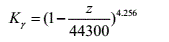 , taking the average altitude of the Guanjiao tunnel area as z=3600m, then
 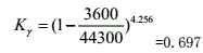 .
.
4.1.9 Take the friction resistance coefficient along the ventilation duct, that is, the Darcy coefficient λ= 0.012~0.015.
4.1.10 The design standard speed of the dump truck is 10km/h, with a slope of about 5° or when the road surface is uneven, the speed is 5km/h
4.1.11 The wind resistance of the air inlet and outlet of the inclined shaft. Take No. 6 inclined shaft (2808m) as an example, after the inclined shaft enters the main hole, construction will be carried out in the direction of entry and exit of Lines I and II respectively, with a total of 4 working faces.
The cross-sectional area of the air inlet duct in the upper part of the inclined shaft is 17.1m2, the semicircular perimeter is 16.96m, and the equivalent diameter is 4.03m. The cross-sectional area of the exhaust duct in the lower part of the inclined shaft is 22.0m2, the rectangular perimeter is 19.88m, and the equivalent diameter is 4.43m.
4.2 Design and System Parameters of Hybrid Ventilation Scheme in Clapboard Roadway of Inclined Shaft
Table 4 shows the design and system parameters of the mixed ventilation in the clapboard roadway of each inclined shaft. For example, in the No. 6 inclined shaft, the 125B-2110 type counter-rotating axial flow fan can be selected. The designed air volume is 1800m3/min and the total pressure is 5000Pa. , The motor power is 2×110kW, and the two-stage speed regulation.
Table 4 Hybrid ventilation design and system parameters of each inclined shaft clapboard roadway
| Inclined
shaft No. |
Inclined shaft
length (m) |
Inlet direction construction
length Linlet (m) |
Outlet direction construction
length Loutlet (m) |
The total air volume Q in the
inclined shaft(m3/min) |
Inlet wind
speed(m/s) |
Exhaust duct
wind speed (m/s) |
Total air flow loss in
inclined shaft h(Pa) |
Finlet | Foutlet |
| 5 | 1935 | 965 | 1088 | 7200 | 7.0 | 5.45 | 1335 | Q=1800m3/min, Ht=2200Pa, N=90kW | Q=1800m3/min, Ht=2200Pa, N=90kW, φ=1.6m |
| 6 | 2808 | 1312 | 1812 | 8400 | 8.18 | 6.36 | 1938 | Q=1800m3/min, Ht=5000Pa, N=2×110 kW, φ=1.6m | Q=2400m3/min, Ht=4100Pa, N=2×110 kW, φ=1.6m |
| 8 | 1619 | 1624 | 547 | 7800 | 7.6 | 5.9 | 1117 | Q=2400m3/min, Ht=4100Pa, N=2×110 kW, φ=1.6m | Q=1500m3/min, Ht=2200Pa, N=75 kW, φ=1.6m |
| 9 | 1126 | 1353 | 518 | 6600 | 6.4 | 5.0 | 777 | Q=1800m3/min, Ht=2200Pa, N=110 kW, φ=1.6m | Q=1500m3/min, Ht=2200Pa, N=75 kW, φ=1.4m |
| 10 | 443 | 3272 | 2406 | 9600 | 9.36 | 7.27 | 306 | Q=2400m3/min, Ht=4100Pa, N=2×110 kW, φ=1.6m | Q=2400m3/min, Ht=4100Pa, N=2×110 kW, φ=1.6m |
Post time: Jul-04-2022